Coordinate System and Wind#
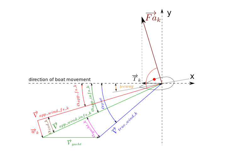
Figure 9 shows wind and force vectors acting on a boat moving along x-axis with the velocity \(\overrightarrow{V}_{yacht}\). The apparent wind velocity for an ‘finite’ sail is described by vector \(\overrightarrow{V}_{app\_wind\_fs}\) (with induced wind velocity).
An aerodynamic force is generated and is perpendicular to \(\overrightarrow{V}_{app\_wind\_fs}\).
Name |
Description |
|---|---|
\(\overrightarrow{V}_{yacht}\) |
angle between apparent wind and true wind |
\(\overrightarrow{V}_{app\_wind\_infs\_k}\) |
apparent wind velocity for an ‘infinite sail’ (without induced wind velocity) acting on k-th panel |
\(\overrightarrow{V}_{app\_wind\_fs\_k}\) |
apparent wind velocity for an ‘finite sail’ (with induced wind velocity) acting on k-th panel |
\(\overrightarrow{V}_{true\_wind\_k}\) |
true wind velocity acting on k-th panel |
\(\overrightarrow{w}\_{k}\) |
induced wind velocity acting on k-th panel |
\(\alpha_{app\_infs\_k}\) |
angle between apparent wind acting on k-th panel for an ‘infinite sail’ (without induced wind velocity) and direction of boat movement (including leeway) |
\(\alpha_{app\_fs\_k}\) |
angle between apparent wind of a ‘finite sail’ acting on k-th panel (with induced wind velocity) and direction of boat movement (including leeway) |
\(\alpha_{ind\_k}\) |
angle between apparent wind acting on k-th panel of a ‘finite sail’ (induced wind velocity) and apparent wind of an ‘infinite sail’ (without induced wind velocity) |
\(\alpha_{yacht\_k}\) |
angle between apparent wind acting on k-th panel and true wind |
\(\alpha_{true}\) |
angle between true wind acting on k-th panel and direction of boat movement with reference to course over ground (i.e. including leeway) [deg] |
\(\overrightarrow{F}_a\) |
aerodynamic force acting on k-th panel |
\(\overrightarrow{T}\) |
thrust force in direction of boat movement - Speed Over Ground (SOG) |
\(\overrightarrow{D}\) |
drag |
\(\overrightarrow{L}\) |
lift |
\(\overrightarrow{U}_{\infty}\) |
free-stream with uniform velocity |
COW |
Course over Water |
COG |
Course over Ground (along x axis) |
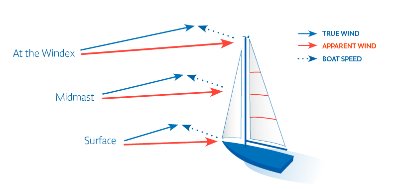
Due to surface friction, the profile of the true wind is logarithmic. As a consequence, the profile of apparent wind is twisted (see figure 10).
Due to tip vorticies (shown at figure 11) extra wind \(\overrightarrow{w}\) is generated.
As a consequence, resulting wind velocity \(\overrightarrow{u}\) acting on a lifting surface is different than free stream and is the sum of the vectors \(\overrightarrow{u}_{\infty}\) and \(\overrightarrow{w}\). Therefore, the induced wind causes additional drag \(\overrightarrow{D}\). In conclusion, the resulting aerodynamic force, \(\overrightarrow{L}\), is the sum of \(\overrightarrow{D}\) and \(\overrightarrow{L}_{\infty}\) vectors (figure 12).
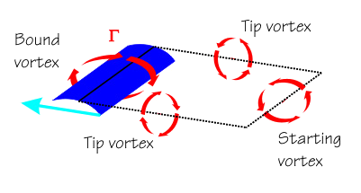
Fig. 11 The induceed wind is generated by trailing vortices. It causes additional drag. Figure 6 from [tip].#
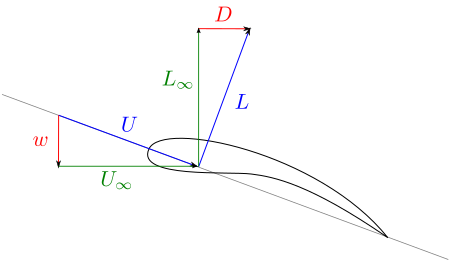
Fig. 12 Extra drag generated by induced wind. Figure 6 from [Gru21].#
Induced drag is proportional to the square of lift (depicted in Figure 13). There exists an unique value of lift and the drag induced by it, for which the thrust reaches maximum. To minimise drag, the right shape of sail should be chosen.
